 Figure 1: The vibration isolation curves. Figure 2: The shock isolation curves.
Problem Statement
The goal of the design project is to develop a video camera mount that can be used on any vehicle to record the experience of traversing a rough, off-road trail. Our design will concentrate specifically on mounting the system on a mountain bike. The problem with bolting a camera to a bike is that the constant vibration from the trail’s rough surface degrades the quality of the video picture. Additionally, the repetitive and sometimes severe shocks endured by a bicycle may damage the camera. In order to solve this problem, we have proposed to design and construct a video camera mount that absorbs vibrations. The desired result is a picture that is continuous and smooth.
Design Requirements
To help define the boundaries of the project, we have developed a list of design requirements for the camera mount. The vibration isolation system must:
Brainstorming/ Morphological Chart
Before we settled upon our final design, much time was spent developing and investigating different options for the vibration isolation mechanism to be used. On the following page is a morphological chart, which outlines our decisions and shows how our design changed slightly throughout the span of the entire project.
Math Model
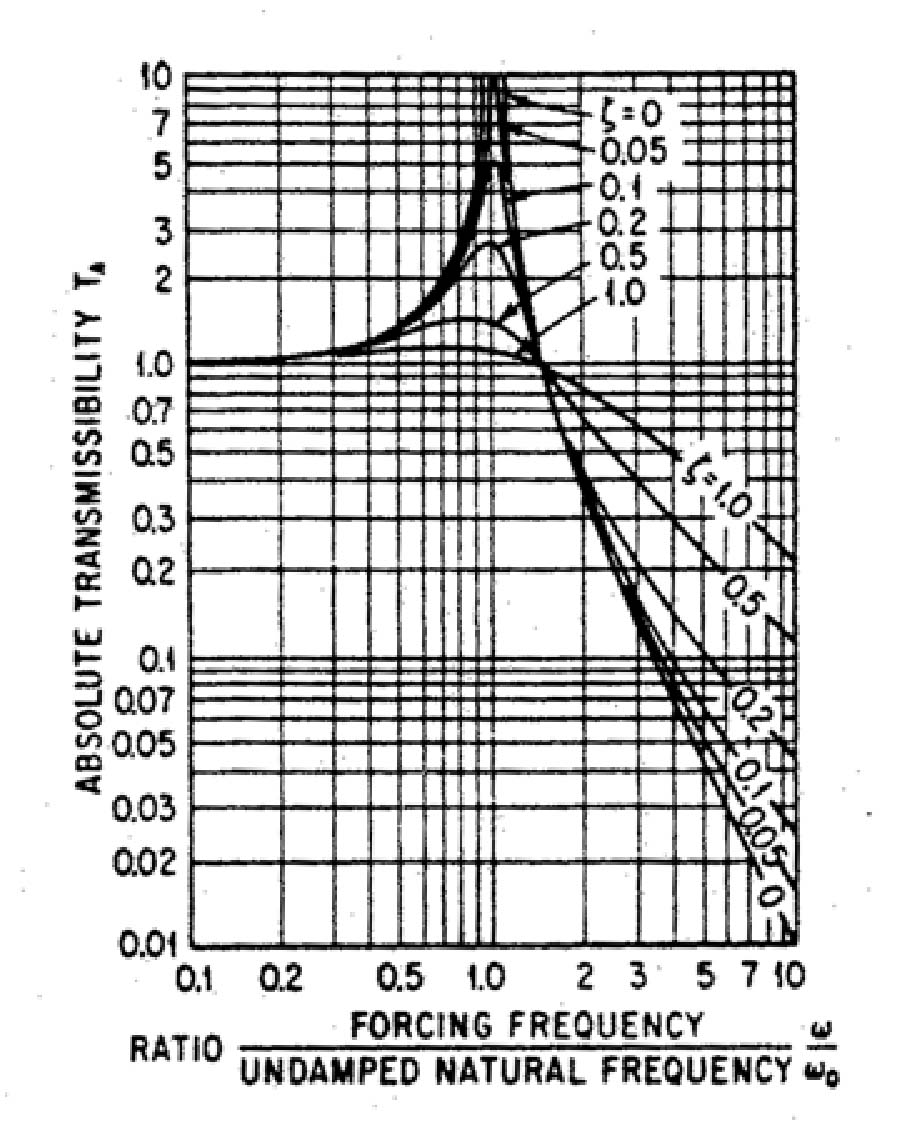
The main mathematical model that we used is the vibration isolation table (figure 1). The key point of the table occurs when the forcing frequency is equal to the natural frequency of the system. At this frequency, a damping factor of 1.0 is desired to minimize the transmissibility of the system. At frequencies above the square root of two times the natural frequency of the system the transmissibility is less than one, and the camera will not move as much as the bike. At higher frequencies, less damping is desirable in order to minimize the response.
Figure 1: The vibration isolation curves. Figure 2: The shock isolation curves.
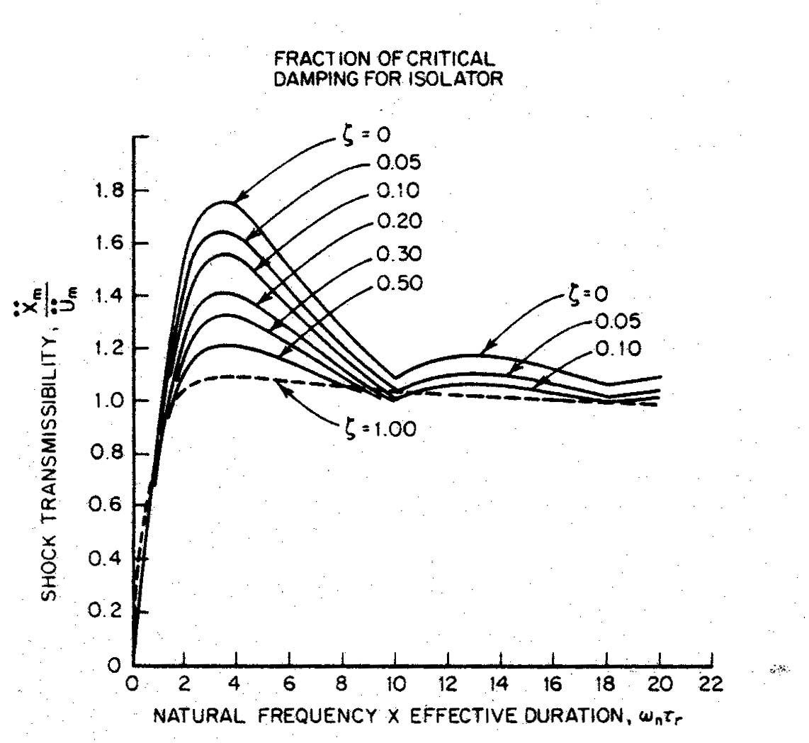
While we also considered the shock spectrum (Figure 2), it was very difficult to get an idea of the effective duration of the input impulses. Because of our uncertainty, and our current lack of understanding of the shock spectrum, we chose to continue this line of questioning in the future (see Future Line of Work).
Synthesis
In order to build a strong, low friction, one degree of freedom system, we chose to utilize two parallel four-bar linkages. By using the four-bar linkage, we can easily achieve a high degree of travel and provide adjustability of spring rate, natural frequency, etc. The dimensions of the four-bar mechanism were selected to be cost-effective and easily manufactured while still operating within our constraints. In order to model different four-bar linkages, we developed a spreadsheet that could effectively model our system. This spreadsheet is located on page 1 of the Appendix.
In order to gain the most control over our system, we decided to use high precision anti-friction bearings and a fluid damping system. With these components, we retain control over the amount of friction in our system (thus control over the damping) and we can easily make future changes to our product. In addition, we designed our spring mounting system to be used with different spring rates in different positions. This allows us to modify the static position of the camera, adjust the natural frequency of the system, and switch to a heavier or lighter camera.
Our design has small bumpers to constrain the system to plus/minus thirty degrees of control arm movement from the horizontal position. These bumpers were installed to keep the system from moving outside of the working range and damaging parts. The bumpers effectively increase the k-value of the spring in a non-linear region located at the edge of the working range. This does, however, introduce impact loading when the arms strike the bumpers.
Analysis
Because of the large number of stress and fatigue calculations (listed in the Appendix), only the critical computations are listed below. Because of the dynamics involved with our system, we assumed the maximum acceleration of the camera platform to be 5 times gravity (5 g’s). In addition, we assumed that we were operating within the design parameters, neglecting impact. In reality, when the camera platform hits the rubber bumpers, there will be a magnification of load due to that impact.
Table 1: Areas of Critical Stress and Associated Safety Factors.
Because the ShockCam 2000 undergoes cyclic loading, fatigue played a key factor in our design. Below are some of our components and their expected life.
Table 2: Fatigue Life Data of Critical Parts.

Manufacturing/ Production Needs
Much effort was put into making the design as simple as possible in order to reduce the overall cost and manufacturing time, but still fall within the design requirements and achieve acceptable levels of aesthetics, reliability, safety, and performance. 6061-T6 aluminum was chosen for all of the machined parts due to its high strength, low weight and cost, resistance to corrosion, wide availability in many sizes and forms, and ease of machinability. The manufacturing methods used for the prototype had to limited to mill and lathe operations in order to produce the prototype in a reasonable amount of time. All of the fasteners used are Type 304 stainless steel since resistance to corrosion is a primary concern for a product that will spend much of its life outdoors in dirt and mud.

Figure 3:
Machined parts on the shop floor.
The overall size and weight of the unit was kept to a minimum to reduce any adverse effects the system may have on bicycle handling and rider ergonomics, as well as overall aesthetics of the vehicle. Placing the camera platform inside the 4-bar mechanism protects the camera from damage, lowers the system’s center of gravity, and reduces the effective moment of inertia the rider feels in the steering.
Fortunately, even a total failure of the system poses little threat to the rider’s well-being. Extreme damage could occur, however, to the expensive and fragile video camera. The nature of the four-bar mechanism offers redundancy in the event of a failure of any single part. Having two linkages and a spring on each side would allow time to notice the failure and stop the vehicle before total structural failure and damage to the camera occurred. In addition, safety factors are high due to the oversize parts resulting from using standard-sized aluminum stock and fasteners with a minimum amount of machining. (More on safety factors in the Analysis section.)
The cost of the prototype was relatively high at $250 just for parts and materials. The use of stainless steel fasteners and bearings added considerably to the cost, as did the 12-volt solenoid valve and the circuit to run it. A more complicated sensing system to actively change the damping was out of the question since accelerometers and vibrometers are several hundred dollars each. (More on cost reduction in the Critical Review section.)
Attainment of a damper that fit into the design requirements was difficult. The size of the required unit was unique and much time was consumed in its location and purchase. The use of the internet in gathering data on parts and purchasing supplies was extremely helpful throughout the project.
Testing Plan
In order to test the ShockCam 2000, we decided to run it in the vibrations lab and out on the trail. Taking our camera off-road is obviously very important. We are concerned, however, with the safety of the video camera, and this is the reason that we will do the initial testing in the controlled environment of the vibrations lab. This is also the reason that we will be using a calibrated mass instead of a camera for most of the testing.
In the vibrations lab, we will look at the Shock Cam 2000’s response to various inputs. We will test the 2000 with a random noise input and a sinusoidal input at the natural frequency. By looking at a random noise input with a span of 250mHz to 10 Hz, we feel that we can simulate trail conditions. We will adjust the amplitude of the shake table displacement from 0.5 inches to 2 inches. The input amplitude is not critical, as we are concerned with the ratio of camera displacement over shake table displacement. We will calculate this ratio by placing a vibrometer on the shake table and an accelerometer on the camera platform. We can then run these signals into an FFT analyzer and display the data as a Bode diagram. We will run this experiment with varying degrees of damping in order to show how damping affects the motion of the camera platform. We will also run the shake table at the platform’s natural frequency in order to simulate a "worst case" scenario.
Once we are confident in the ShockCam’s ability to protect the camera, we will run some field tests. We will start out by riding around on pavement, then work our way up to hopping curbs, concluding testing in a full-blown field ride.
Smartness
The Shock Cam 2000 is equipped with some smartness to operate the damper. The damper we used in our project can be electronically controlled by a 12-volt solenoid valve. In order to operate the valve, we attached a simple circuit with an on/off button located right on the bicycle handlebar. The person who is riding the bicycle will leave it off when he is going in a small high frequency bump area and turn it on when he reaches large magnitude low frequency bumps or when he thinks the units is going to start bottoming or topping out. We also attached an LED, which indicates when our damping is activated. Unfortunately, the solenoid valve orifice sizes were not exactly what we were looking for, so for testing purposes we removed the solenoid and replaced it with an infinitely adjustable needle valve. The idea is to determine the correct open and closed valve positions and then modify our solenoid to match these dimensions. This modification would require a new hole to be drilled in the valve and another to be reamed out to a slightly larger diameter.
Figure 4:
The solenoid used in our damping circuit.

Figure 5: The completed prototype with hydraulic damper installed.
Testing Correlation
Overall, the testing agreed with our original projections. The ShockCam is fairly easy to set up and use. The bulk of the camera is not as noticeable to the rider as we thought it would be. The parts all move smoothly, and the damping is easily adjustable.
 Figure 7: The response of ShockCam 2000 to a random noise signal.
 The ShockCam isolated vibrations in the high frequency region much better than in the low frequency region. A comparison of the vibration isolation curve (Figure 1) and the experimental result curves (figure 7) shows the correlation in the frequency domain. Also it is notable that in the high frequency range the response was decreased as damping was decreased. This is evident in the vibration isolation curve as well as our experimental results.
Figure 8:
Working with the hydraulic shake table.
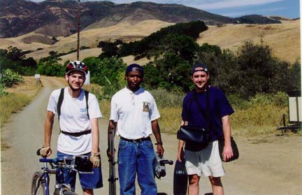
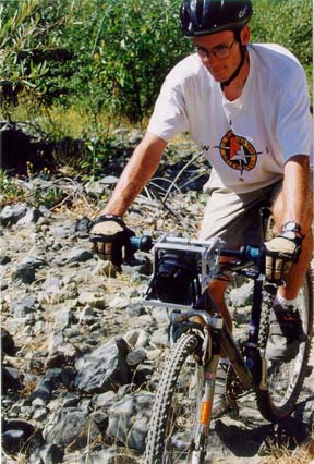
Figure 9:
Trail Testing in Stenner Creek.On the trail, we found that there was too much shock being transmitted to the camera. This was evident in the small sharp bangs that could be heard every once in a while. The picture quality was not as good as we had hoped, but the camera survived all of our abuse.
Critical Review
While conducting a critical review of our design, we came up with the following shortcomings:
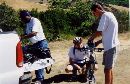
Figure 9:
Tweaking the system on the trail.
Conclusions
While working on this project, we learned about the design process and what is required to take a design from a brainstorming session all the way to field-testing and real-world abuse. We were also able to incorporate our new design skills learned in the ME 328 and ME 329 lectures. Another valuable skill developed during this project was the ability to work with others in a team environment-- communicating ideas, combining effort toward a common goal, and compromising when all members didn’t agree in order to achieve the desired result.
Future Lines of Work
While the quarter is coming to an end, we continue to find further items that need improving (see Critical Review above). Further lines of inquiry would include:
Harris, Cyril M. Shock and Vibration Handbook.
1996. McGraw-Hill. New York.
Rothbart, Harold A. Mechanical Design and Systems Handbook.
1964. McGraw-Hill. New York
Timeosheko. The Theory of Elasticity
Juvinal, Robert C., Kurt M. Marshek. Fundamentals of Machine Component Design.
1993. John Wiley & Sons. New York