Robomouse Telemetry Project
by
Terry Smiley
Mechanical Engineering
Department
California Polytechnic State
University
San Luis Obispo
2000
Statement
of Disclaimer
Since
this project is a result of a class assignment, it has been graded and accepted
as fulfillment of the course requirements.
Acceptance does not imply technical accuracy or reliability. Any use of information in this report is
done at the risk of the user. These
risks may include failure of the device or infringement of patent or copyright
laws. California Polytechnic State
University at San Luis Obispo and its staff cannot be held liable for any use
or misuse of the project.
Table
of Contents
Section Page
Abstract 1
Introduction 2
Background/Noise 3
Dataflow 4
Programming 8
Robot
Construction 10
Procedure 13
Discussion
and Recommendation 14
Bibliography 16
Appendix
A.
Robosoccer: Rules and Information 18
B. Transmitter Wiring Diagram 19
C.
Receiver Wiring Diagram 20
D.
Schematics: MAX 233 and EDE 300 21
E.
Schematics: Ming TX-01 and Ming TX-99 22
F.
Schematics: Ming RE-99 and Ming RE-01 23
G.
Schematics: Parallax Stamp II 24
H.
Parts Information 25
I.
Transmitting Program 27
J.
Mobile Robot Program 29
Figures
Illustration Page
1. Radio Noise 3
2. Signal Waveform 3
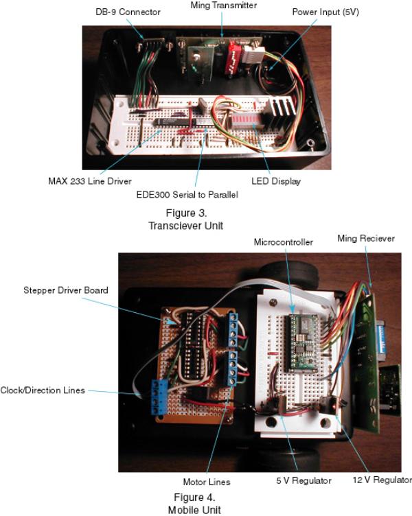
3. Transceiver Unit 5
4. Mobile Unit 5
5. 1st View of Mobile Robot 11
6. 2nd View of Mobile Robot 11
Abstract
This
report outlines the design, construction and use of a simple 4 bit one way
wireless communication system between a DOS based personal computer (utilizing
the RS232 serial protocol) and a TTL level device (such as a mobile robot). In addition, specifications are given for a
proof-of-concept mobile robot. The
report includes wiring diagrams and sample programs in addition to the design
specifications and build procedures.
Introduction
The
object of this project was to design and build a simple, cost-effective
communication link between a personal computer (PC) and a small semi-autonomous
mobile robot (robomouse). This link
will transmit simple instructions to be carried out by the robot (forward, left,
right, etc.). The system was to be designed
to be compatible with a “robo-soccer” type event.
Robo-soccer
(also called robotic football) is a relatively new competition at different
international mechatronics/robotics conventions. The event consists of two teams of 3 robots each that play soccer
against each other with a golf ball on a ping pong sized field. The robots are monitored by an external
global vision system that then controls each of its robots via wireless links. For some sample rules and robots see
Appendix A, figures A1 and A2.
Building
a team of robots and the vision system to run them is a large task, but it can
be broken down into several smaller projects among different engineers. My goal
was to design and fabricate an inexpensive one way radio link between a
personal computer running DOS or Windows and one of the robots. Other engineers would concentrate on the
robots themselves, the vision system to monitor the robots, and the computer
program that makes strategic decisions and outputs the necessary data to my
radio link.
While
many wireless applications require two way data transfer, a two-way system is
unnecessary and expensive for certain processes. Although this design was developed with robo-soccer in mind,
there are many other practical uses for one way data communication. One of the most common uses is data
telemetry from a remote site to a computer (basically my system running
backwards). The remote site could be an
autonomous robot out collecting data, a race car on a closed track, or a
spacecraft sending back collected data.
Some
Background: Noise in Serial Radio Communication
While
wireless serial communication seems like a simple extension of wired serial
communication, it brings with it a host of new problems to be solved. Many of
these problems are based on the fact that low power radio signals have a
tendency to get distorted over time and space.
When
an AM radio transceiver sends an encoded signal it is modulating the amplitude
of the fixed frequency radio wave around a preset amplitude. The receiver can then look at the relative
highs and lows of the incoming radio waves (at the particular frequency) and
will determine whether it is a high or a low.
Problems arise when random noise in introduced to the radio wave and the
receiver cannot distinguish the noise from the real signal. A beneficial characteristic of this noise is
that in the 300 MHz range the noise tends to be in the form of upward spikes
during the low portion of the cycle, rather than downward spikes during the
high portion (see Figure 4 below).

Figure 1
Noise that may be introduced
into a radio signal
Because
of the nature of these upward noise spikes, we can reduce the error in our
system by maximizing the high portion of the signal. Figure 5 below shows an example of how an 8-bit data stream (with
a preamble) can be encoded to maximize the high time.
Figure 2
Maximizing the high portion
of an encoded signal
This
is just one way of reducing the error due to noise. Other ways include methods of error checking (such as a check-sum
system) or having the mobile application mirror the signal back to the base
comparison (requires two-way communication).
Flow of Information
This
project is all about getting information from one place to another. In order for this information to be sent
from the computer to the robot the data must be transformed several different
times. In this project the data goes
from the machine language of the PC to RS232 serial data to 4 bit parallel
data, where it is appended to an 8 bit address code. This 12 bit data is then serially sent by the encoder to the
transmitter where it is converted into a 300 MHz amplitude modulated
signal. This signal is received by the
receiver, converted to 12 bit parallel data (where the 8 bit address code is
verified), and then the 4 data bits are input into the microcontroller or
microprocessor as TTL level voltage.
The wiring diagrams for both sides of the systems (transmitting and
receiving) are located in Appendices B and C.
There is also a parts list with prices and ordering numbers located in
Appendix H.
Computer machine language to
RS232 (in computer)
With
this particular project I chose to use the C language because of its
simplicity. The program is set up to
output ASCI text to the COM1 port at particular times. The C program uses the BIOS library
functions to serially output this code in the RS232 form.
RS232 to serial TTL (in
“black box”)
Because
RS232 levels are 0 V and –13V they are not compatible with regular TTL level
chips (0V and 5V). Because of this, I
used a MAXIM Max233 RS232 receiver to
convert the signal into the standard TTL format. Please see the Max 233 pinout in Appendix D.
Serial TTL to parallel TTL
(in “black box”)
While
I could have transmitted the serial signal directly, I found that the error
checking functionality of the standard serial signals are not sufficient to
handle the noise inherent in low power wireless systems. Therefore I chose to utilize an exiting low
cost encoder/transmitter pair from Ming
Microsystemsä.
Because
the Ming system utilized parallel
input/output, I had to first transform my serial signal to a parallel one. To do this I used EDE300 Parallel/Serial
Transceiver IC from elabä (see figure D2, Appendix D for more
data). The elab IC took the TTL
level serial data and converted it into 8 bit parallel data, of which I used
the 4 least significant bits.
Parallel TTL to encoded
serial (in “black box”)
Early
in the project I had planned to encode the serial data using C and transmit
that over the radio signal, but this proved to be extremely difficult to do
with any consistency. Noise and error
checking are a large concern with radio signals, and with the nearby computer
the noise was even worse. The biggest
problem though, was the fact that if I were to do my own custom encoding then I
would have to write a complex routine to decode that signal, and this routine
would have to be carried out by the microprocessor on board the mobile
robot. While this is possible, the
robot’s processor is likely already going to be busy moving around or
collecting data, so a dedicated decoder is desired to free up that valuable
processing power. The Ming system is affordable and easy to
use, so it lent itself to this task (encoding and decoding, as well as the
radio transmission/reception).

Before
the encoder converts the 4 bit parallel input into a serial signal, it adds an
8 bit address to the beginning of the input.
This is a dip-switch set input that lets the encoder and decoder check
for errors. Next this 12 bit data goes
into the encoder. Because the Ming system utilizes a proprietary
encoding scheme I do not know the details, but it likely looks something like
the signal seen in Figure 5. This
signal could be determined with a high-speed oscilloscope but I felt that it
was beyond the scope of this project.
See figure E1, Appendix E for a wiring diagram of the encoder.
Encoded signal to 300 MHz AM
radio signal
The
transmission unit creates a 300MHz carrier signal that is broadcast throughout
the area as radio waves. Once the
analog circuit creates this signal it is modulated using the serial signal from
the encoder. This particular
transmitter uses amplitude modulation (AM), so the data signal is used to alter
the amplitude of the carrier signal. It
is the relative highs and lows in this modulated carrier signal that transmits
the data over the radio waves. See
figure E2, Appendix E for a circuit diagram of the transmitter.
300 MHz AM radio signal to
Encoded signal
Essentially
this is the reverse process of the transmitting routine. The receiver samples the radio waves in the
air and determines the relative highs and lows (amplitude) on the 300 MHz
frequency, sending them out as an encoded serial stream to the decoder. See figure F1, Appendix F1 for a circuit
diagram of the receiver.
Encoded signal to parallel
TTL
The
Ming system uses its own system for
decoding the encoded serial input. It
then checks the signal’s 8 bit address against its own 8 bit address (set with
dip-switches) to look for a match. If
these addresses do indeed match, the 4 bit data on the signal is output as
parallel TTL level data. This data can
then be used to control various actions.
See figure F2, Appendix F for a
wiring schematic of the decoder.
4 bit parallel TTL to microcontroller
Once
the 4 bit data is output from the decoder it is very easy to input into a
microcontroller or microprocessor. I
had originally planned to use a serial input into a microcontroller, but I felt
that by building the device to the specifics of say, the Motorola SCI
interface, I would be limiting the potential of the device. Instead, I chose to use simple 4 bit TTL
level data that can be input into a microcontroller port directly or through a
peripheral type system. Because of this
functionality, the radio link can be used on a Motorola 6802, a Motorola
6805, a Parallax Basic Stamp, or any
number of other microcontrollers/processors.
With my robot I chose to use the Basic Stamp II from Parallax. See Appendix G for a pinout of the Stamp.
Interpreting the 4 bit data
The
microcontroller/processor can deal with the incoming data in one of two
ways. The first method is for the
microcontroller to periodically poll the input lines, that is, check them
frequently, to see what signal lies there, and run the program
accordingly. Because my microcontroller
is very dependent on the input lines (it won’t run without the radio link), I
chose to utilize this method. The other
way to receive the data would be to have one of the data bits sent to the interrupt
request pin (IRQ or equivalent) on the microcontroller and have the interrupt
service routine check the radio input pins.
This would be a good solution to a remote application that only needs to
receive data intermittently and doesn’t want go through the time-consuming
process of polling the input bits.
Computer
Program (Transmitting side- PC)
The
computer program, written in Borland C, is designed to be a demonstration
program, and not really for use with an actual task. The program prompts the user for command information, speed
setting, and duration of motion, and then outputs these parameters to the COM1
port where they are sent to the mouse.
An annotated copy of the program is located in Appendix I.
A
more useful program would be tailored to meet the needs of the actual
problem. Such a program could take an
input data stream and output the data at different times. This would be ideal in the situation where
the input data stream came from a vision system or a joystick or some other
“real time” feedback device. The data
stream could also be produced from a .dxf drawing (like an AutoCAD drawing) of
a prescribed course. AutoCAD has
plotter outputs that could be converted (with yet another program) into an
appropriate data stream. With this
functionality an operator could load a drawing of the Mechatronics obstacle
course and the computer would be able to instruct the mouse on how to navigate
it.
The
program works like many simple DOS programs to take user input and modify it
into data that can be sent to the robot.
It does this by means of ASCII manipulation through if/then statements, while
and for loops, and the _bios_serialcom statement, which outputs
the data to COM1 (as it is set up). The
program also has a 3-digit time input, which sets the time that the command is
output to the robot. The program is
designed to run indefinitely, or to exit when the user types the letter q (for
quit). This program could be upgraded
to C++ with a windows environment fairly easily, but it is beyond my
programming skills at this point.
One
of the nice aspects of the PC/transmitter interface is that it is highly
portable. The transmitter attaches to
the PC via a DB-9 cable to the COM1 port on the PC and the transmit program can
run off of a floppy disk. Because the
transmitter unit incorporates serial to parallel conversion, no digital I/O
card is necessary on the host PC. I can
run this setup off of a cheap PC or a notebook computer without any additional
cost or set-up.
Computer
Program (receiving side)
The
receiver program is written in PBASIC and is designed to run on a Stamp II
microcontroller, but could easily be written for a Motorola or and Intel
chip. Because the radio data is coming
in on a 4 bit parallel bus, all we need to do is have the program poll the
input ports connected to this bus. The
program can then make logical decisions based on the state of this port. This setup can easily be used with a ME 405
micromouse running the Motorola 6802 processor.
I
chose to use the Stamp II microcontroller because of the fact that I could
program/debug the unit from the comfort of my home. The onboard EEPROM is sufficient to hold a simple program and the
processor is powerful enough to handle the simple tasks it is asked to
accomplish. The Stamp II is also very
well documented and can be used in a number of different situations.
My
program (located in Appendix J) first assigns variables based on the input bits
(from the radio link). First it
compares the first radio bit (on/off bit) to logic low and if they are equal it
stays at this location in the program, keeping the motors from running. If the first radio bit is high, the program
is allowed to proceed to the next step, where the speed is set to either high
or low. Next the two direction bits are
checked to see what direction we want to go.
Depending on these values (there are 4 combinations) the program
branches to a subroutine that actually pulses the motors in the correct
orientation for that motion. The speed
that is set at the beginning of the program is used in these subroutines to
pulse the motors for the right amount of time.
After the pulse has been sent to the motors the program returns to the
beginning to start all over again.
Because the program checks the radio bits continuously the
microcontroller is very quick to respond to changes in their status. You can be sure that the robot will not take
a single step in the wrong direction (pun intended).
Robot
Construction
The
mobile robot that carries the Basic Stamp II is made up of 5 basic
components. There is a frame,
motor/wheel assemblies, the motor driver board, the microcontroller board, and
the radio receiver. Below I will outline the functionality and basic design of
each of these parts. It is important to
remember that this robot was designed and built to be a proof of the radio
concept, and is therefore not necessarily the best design (it’s not!).
Frame:
The
basic frame is a simple project box from Radio Shack that has been heavily
modified to suit the task. I chose a
plastic box because I felt that the relatively low weight, the high stiffness,
and the low cost justified the decision.
The box has been inverted and the walls have been shortened with a
Dremel to save weight. Mounting holes
have been drilled and the back wall has been modified to accept a small rear
castor wheel. The frame could be made
significantly lighter (while maintaining stiffness) by drilling and shaving
unnecessary material away.
Motor/Wheel
assemblies:
With
this robot I chose to use a belt driven wheel assembly. The reason I did this was to get both drive
wheels on the same axis. The front axle
is fixed and the wheels are free to rotate about it. Attached to each drive wheel is a sprocket which mates to a
toothed belt. These belts mate to the
pinon gear that is press fit onto the stepper motors. The sprockets and belts were obtained from an old HP printer;
they were used with a DC motor to drive the print head back and forth over the
paper. The wheels were left over from
an old project, and are likely from a remote controlled airplane. Smaller, more precise wheels are an obvious
improvement. The motors are mounted to
the frame via 2-56 hardware.
Motor
driver board:
The
motor driver board was actually left over from my ME 405 project (although it
was never used). I constructed it based
on the circuit diagram provided by Dr. Yong on a piece of perfboard. Screw type terminals were added to
facilitate hookups. The board provides
a basic platform for two Motorola 3479 Stepper driver chips. Each of these chips receives two signals
from the microcontroller: a direction (CW or CCW) signal and a clock
signal. The chips automatically
sequence the output (motor) wires in the proper order, and keep track of the
current position of the motor. The
chips also provide power to the motors, so no external power transistors are
necessary.
Microcontroller
breadboard:
The
microcontroller breadboard serves two functions: providing a platform for the
mounting of the Parallax Basic Stamp II and regulating the power coming in from
the batteries. The platform for the
Stamp II is just a connection box for the inputs (the 4 radio signal lines) and
the outputs (the two sets of two motor control lines). The platform also makes the necessary power
and ground connections. The power
regulation section of the breadboard steps the 18 V input voltage down to two
voltages: twelve volt and five volt supplies.
The twelve volt power is used by the radio receiver and the motor driver
board, they require extra power to do their tasks. The five volt supply is used to power
the
microcontroller. The different supplies
share a common ground. The
microcontroller breadboard is mounted with 2-56 hardware.
Radio
receiver:
The
radio receiver is pretty well covered in the information flow section of the
paper. It is sufficient to say that it
receives the data from the modulated 300 MHz radio signal and then decodes and
outputs the data on a 4 bit parallel bus.
This 4 bit bus connects to the microcontroller breadboard. There are also power and ground lines that
connect to the voltage regulators, as well as a pair of lines that are
connected to a relay on the radio receiver.
This relay is closed whenever the radio receiver is in contact with the
transmitter, and can be used to stop a runaway mobile robot.
Procedure
to Operate Device
As
the system is currently constructed, the following steps should be taken to set
up all of the components:
The
transmitter (“black box”) needs to be plugged into its power supply. The supply should be 12 V DC, with the
positive pole on the inside of the plug.
The
transmitter should then be connected to a PC via COM1 and a DB-9 serial
cable. This is the smaller style of
cable with nine pins. If the computer
does not have COM1 available or there is not a DB-9 hookup, find the address of
a free serial port (using the computer’s BIOS settings) and rewrite that
portion of the software.
Once
the transmitter is hooked up, run the software off of a floppy or hard
disk. The program should be entitled
“radio.exe”. It can be run through DOS
or Windows.
Plug
the batteries into the robot. There
should be four 9V battery connectors and clips for these batteries.
The
program ought to prompt the user for an input.
The first input should be the type of motion desired. This will either be f (forward motion), b
(backward), l (left pivot), or r (right pivot).
The
program will now prompt the user for a speed.
There are currently only two choices, fast (f) and slow (s).
At
the next step the user is prompted to enter the duration of motion. This is a three digit number that
corresponds to hundredths of a second.
For example, entering 567 will yield a run time of 5.67 seconds. The divider (1/100) can easily be changed in
the software if longer periods are desired.
After
the three digit number has been entered, the user merely pushes enter and the
robot should run. The small green LED
on the outside of the transmitter should be lit during run time. Also, if the radio link is active (even when
the robot is stationary), the small green LED on the robot should be lit.
When
the motion has been completed, the program will prompt the user to hit another
character. When the user is done with
the program, “q” will quit the program, as will clicking the close button (in
Windows).
Discussion/Recommendation
When
this project was first conceived it was thought to be a part of a robo-soccer
competition, and it will still serve that purpose well. If the project were to be linked up to a
vision system (providing visual feedback) this could become a very powerful
platform. While robo-soccer is a great
way to introduce technology, it is not commercially viable and thus new
applications need to be explored.
One
possible avenue to explore is digital telemetry, the transfer of data from a
remote source back to the PC. To
convert this system to a data collector is very simple, it would require some
rewiring and wouldn’t be too difficult.
The data collector could be one of several types. It could be on a mobile platform, such as a
model rocket, a human powered vehicle, a model airplane, a kite; the list is
long. It could also be hooked up to a
fixed but remote system, such as a solar powered weather station, a volcanic
monitoring station, or a high mountain snow depth gage. All of these uses have the potential for
wireless digital communication, and they do not necessarily require high baud
rates. With an estimated one-time cost
of around 100 dollars this design is affordable enough to be used for small
developmental projects where high speeds and complex encryption are
unnecessary.
The
soccer-robot project could be extended through several other senior
projects. One project would be to design
and build the three small robots. They
should be compact and quick. The robots
could easily be controlled with a microcontroller, perhaps a Motorola 6805 or a
Stamp. The radio links would be my
system, with three different radio frequencies (transceivers and receivers are
available in different frequencies) all running a modified version of my
transceiver program on a single PC. I
would suggest DC servomotors for the drive wheels because of their high torque to
weight ratio. Rechargeable Ni-Cad batteries
(small radio control car batteries) would be a good choice for power.
Another
project would be to develop the vision system necessary to direct the cars in
the proper directions. The vision
system would not only have to recognize the three robots under its control, but
also the three opposing robots and the ball and the soccer playing field. This would be a rather complicated
undertaking, but there may be commercial software packages that would simplify
the process.
The
really challenging project will be the artificial intelligence needed to
interpret the data provided by the vision system and send the proper
instructions to the robots. This would
have to include strategic decision making as well as position and velocity
analysis. The robots need to know where
to go and how fast in order to keep the ball out of their goal and score on the
opposing goal. The software could also
be programmed to interpret the opposing team’s maneuvers and try to base the strategy
on the current situation. This is
obviously a large undertaking and would be suitable for a multi-person senior
project team, perhaps with computer science majors included.
As
challenging as this project sounds, I think that it would be a lot of fun and
everyone involved would learn a lot. It
is the sort of cutting edge design solution that Cal Poly is getting a
reputation for and should continue to pursue.
It would be really exciting if some day Cal Poly were able to compete in
this sort of competition on a national or international level, especially if
all of the work is done by undergraduate students.
Another
option is modify the competition so that it is simple enough to undertake as a
campus-wide competition, much like Robo-rodentia. Perhaps the Mechanical Engineering department could make such a
competition part of the ME 405 or 406 curriculum.
One
problem with these sort of senior projects (and senior projects in general) is
the high cost of construction. It would
be really helpful if there were more resources (I realize there are some) for
parts and money. Perhaps a mechatronics
“library” of motors, actuators, and chips that students could borrow from when
working on these types of projects. It
is possible to do this now, but it would help to have a list of available parts
to choose from.
Bibliography
Borland
C++: The Complete Reference. ©1997
McGraw-Hill.
From
BASIC (or FORTRAN) to C and a bit of C++:
Tutorial by W.M. Kays. (unpublished material)
M68HC05
Family- Understanding Small Microcontrollers- Rev. 2.0. ©1998 Motorola
Circuits,
Devices, and Systems- Fifth Ed. ©1992
John Wiley & Sons.
BASIC
Stamp Programming Manual- Version 1.9.
©1998 Parallax, Inc.
Sales/Technical
Support Manual- 315MHz RF Modules.
©1998 Parallax & DVP, Inc.
ME
405 Notes and Schematics: Y.C
Yong. (unpublished material)
Appendix
Appendix A. Robosoccer Rules and Information

Figure A1.
Rules for a
robo-soccer event
Figure A2.
An article on a robo-soccer
team.

Appendix D.
Schematics
Figure D1.
Pinout for EDE300
serial/parallel converter
Figure D2.
Pinout and schematic for
MAX233 RS-232 Receiver
Appendix E. Schematics
Figure E1.
Wiring diagram for TX 01
Encoder Motherboard

Figure E2.
Wiring diagram for TX 99
radio transceiver
Appendix F.
Schematics
Figure F1.
Wiring diagram for RE 99
radio receiver

Figure F2.
Wiring diagram for RE 01
decoder motherboard
Appendix G. Schematics
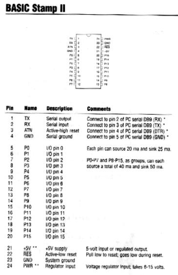
Figure G1.
Pinout for Parallax Basic
Stamp II
Appendix H. Parts List/Descriptions
(Sources and prices may not
exactly match built prototype)
Parallax Stamp II
Microcontroller
24 pins, Dual-In-Line package
$48.95 (Jameco Part No. 130892)
See
pinout page 24
E-Lab EDE300 Parallel/Serial
Transceiver
18
pins: Dual-In-Line package
$12.95
(Jameco Part No. 141541)
See
pinout figure D2 page 21
Ming Microsystems RE-99 RF
Receiver Board
5
v. operating voltage
$11.68
(Digikey Part No.RE-99V3-ND)
See
analog circuit figure F1 page 23
Ming Microsystems TX-99 RF
Transmitter Board
5
v. operating voltage
$10.00
(Digikey Part No. TX-99V3-ND)
See
analog circuit figure E2 page 22
Ming Microsystems TX-01 RF
Encoder Motherboard
12
v. operating voltage
$16.72
(Digikey Part No. TX-01-ND)
See
circuit diagram figure E1 page 22
Ming Microsystems RE-01 RF
Decoder Motherboard
12
v. operating voltage
$25.12
(Digikey Part No. RE-01-ND)
See
circuit diagram figure F2 page 23
Maxim MAX233 Multichannel
RS-232 Driver/Receiver
5
v. operating voltage
20
pins: Dual-In-Line package
$8.93
(Digikey Part No. MAX233EPP-ND)
See
pinout figure D1 page 21
DE-9 Connector (female)
$1.18
(Digikey Part No. A1001-ND)
DE-9
Cable (Male to Female)
$4.95
(Jameco Part No. 25700)
Experimentor 300 solderless
breadboard
$12.49
(Radio Shack)
10 Segment bar-type LED
$6.28
(Digikey Part No. P10723-ND)
4 MHz timing crystal
$0.94
(Digikey Part No. CTX006-ND)
Hook-up wire
22
gage solid (four colors)
$4.49
(Radio Shack)
Plastic Project Box (x2)
$4.39
(Radio Shack)
Various resistors (x3)
$0.49
(Radio Shack)
12 v, 500 mA wall-type power
supply
$12.99
(Radio Shack)
5 v voltage regulator
$1.49
(Radio Shack)
12 v voltage regulator
$1.49
(Radio Shack)
Assorted small hardware (x2)
$1.49
(Radio Shack)
Approximate
total cost: $200
This
total can be reduced by reusing many old parts. This price does not include the stepper motors, which were
obtained from Dr. Yong.
Jameco’s
phone number is 1-800-831-4242
Digikey’s
phone number is 1-800-344-4539
Radio
Shack is located at 209 Madonna Rd., SLO
Mid-State
Electronics is located at 1441 Monterey St., SLO
Appendix
I. Transmitting Code (C)
//This is a program designed to get
specific input from a user and//
//output the information in a 4 bit code
to COM1, where it will//
//be collected by an RF transmitter
connected to a mobile robot//
//Written by Terry Smiley in April 2000
for ME 462//
#include <stdio.h>
#include <conio.h>
#include <dos.h>
#include <bios.h>
int main(void)
{
char
com; //command code; forward, backward, left, right//
char
dat; //temp. variable used to collect data//
char
spd; //speed code; fast or slow//
char
out; //output character, combination of com/spd codes//
char
hsb; //hundreds bit, used to set delay value//
char
tsb; //tens bit, used to set delay value//
char
osb; //ones bit, used to set delay value//
int
dur; //duration of output signal, made up of hsb,tsb,osb//
long
int a;
char
e='e';
clrscr(); //clears
the screen//
bioscom(0,227,0); //initializes
port 0
while(1) //do while 1 is true (always; signifies infinite loop)//
{ //start of infinite loop (until q is pressed//
clrscr(); //reset
screen//
printf("Please
enter command (press q to quit)\n");
//prompt user//
printf("f...FORWARD\n"); //'menu' options//
printf("b...BACKWARD\n");
printf("r...RIGHT\n");
printf("l...LEFT\n");
dat=getch(); //get char. 'dat' from
keyboard//
if(dat=='q'){goto
end;} //exit program when q is
pressed//
com=dat; //set com equal to dat.//
printf("Please
enter speed\n"); //prompt user//
printf("f...FAST\n"); //'menu'
options//
printf("s...SLOW\n");
dat=getch(); //get char. 'dat' from
keyboard//
if(dat=='q'){goto
end;} //exit program when q is pressed//
spd=dat; //set spd equal to
dat.//
if(com=='b'
&& spd=='s'){out=8;} //check status of com,spd,//
//and
set com accordingly//
if(com=='r'
&& spd=='s'){out=9;}
if(com=='l'
&& spd=='s'){out=10;}
if(com=='f'
&& spd=='s'){out=11;}
if(com=='b'
&& spd=='f'){out=12;}
if(com=='r'
&& spd=='f'){out=13;}
if(com=='l'
&& spd=='f'){out=14;}
if(com=='f'
&& spd=='f'){out=15;}
putch(out); //display character 'out'//
printf("Enter
duration of motion + cr (1/10sec; 3 digit number)\n"); //prompt user//
hsb=getche(); //set hsb to first number
inputted into keyboard//
//display
hsb//
tsb=getche(); //set tsb to second number
input into keyboard//
//display
tsb//
osb=getche(); //set osb to third number
input into keyboard// //display
osb//
getch(); //wait for cr (or any
key)//
dur=((hsb-48)*100)+((tsb-48)*10)+((osb-48)*1); //set
dur. to weighted variable// //proportional
to input value//
_bios_serialcom(1,
0, out); //send 'out' to COM1//
for(a=0;
a<10;++a){ //delay routine with quick exit
(hopefully)//
delay(dur); //pauses for ‘dur’ milliseconds//
}
_bios_serialcom(1,
0, 0); //send 00 to COM1//
printf("\nProcedure
completed: any key to continue\n");
//prompt user//
getch(); //pause until keystroke//
} //end
of infinite loop//
end: //label for quit function//
_bios_serialcom(1,
0, 0); //resets COM1//
return
0;
} //end of main
program//
Appendix J. Mobile Robot Code (PBASIC)
'This is a program written in PBASIC by
Terry Smiley; 4/23/2000
'This program is designed to accept 4 bit
radio data and run two stepper motors ‘accordingly
input 0 'bit
0 of radio data
input 1 'bit
0 of radio data
input 8 'bit
0 of radio data
input 9 'bit
0 of radio data
output 4 ‘motor
1 pulse bit
output 5 ‘motor
2 pulse bit
output 10 ‘motor
1 direction bit
output 7 ‘motor
2 direction bit
'various
initializations
code var word ‘these
variables are used
code0 var code.bit0 ‘throughout
the program
code1 var code.bit1
code2 var code.bit2
code3 var code.bit3
delay var byte
start 'start
of infinite loop
code0=IN0 ‘get values from radio
input lines
code1=IN1
code2=IN8
code3=IN9
if
code0=0 then start 'check
for on/off pin
if
code1=1 then fast 'check
fast/slow pin
delay=30 'set slow speed
goto
direction ‘skip fast
setting
fast
delay=15 'set fast speed
direction
if
code2=0 and code3=0 then backward ‘radio
input lines determine
if
code2=1 and code3=1 then forward ‘motor
directions
if
code2=1 and code3=0 then left
if
code2=0 and code3=1 then right
forward
high
10 ‘sets
motor directions
high
7 ‘sets motor
directions
high
4 'pulse clock
high
5 'pulse clock
pause
delay ‘pause
determines speed
low
4 'pulse
clock
low
5 'pulse
clock
pause
delay ‘pause
determines speed
goto
start ‘back
to beginning
backward
low
10 ‘sets motor
directions
low
7 ‘sets
motor directions
high
4 'pulse clock
high
5 'pulse clock
pause
delay ‘pause
determines speed
low
4 'pulse
clock
low
5 'pulse
clock
pause
delay ‘pause
determines speed
goto
start ‘back
to beginning
left
high
10 ‘sets
motor directions
low
7 ‘sets
motor directions
high
4 'pulse clock
high
5 'pulse clock
pause
delay ‘pause
determines speed
low
4 'pulse
clock
low
5 'pulse
clock
pause
delay ‘pause
determines speed
goto
start ‘back
to beginning
right
low
10 ‘sets motor
directions
high
7 ‘sets motor
directions
high
4 'pulse clock
high
5 'pulse clock
pause
delay ‘pause
determines speed
low
4 'pulse
clock
low
5 'pulse
clock
pause
delay ‘pause
determines speed
goto
start ‘back
to beginning
end ‘end
of program